Next: Evaluation of Methods to Locate Emission Lines From Calibration Lamps in 2D Spectroscopic Data
Up: Data Processing Systems
Previous: Maintaining Software for Active Missions: a Case Study of Chandra's CTI Problem
Table of Contents -
Subject Index -
Author Index -
Search -
PS reprint -
PDF reprint
Spitzbart, B. D. & Wolk, S. J. 2003, in ASP Conf. Ser., Vol. 314 Astronomical Data
Analysis Software and Systems XIII, eds. F. Ochsenbein, M. Allen, & D. Egret (San Francisco: ASP), 804
Chandra Long-Term Trending and Prognostication Tools
Bradley D. Spitzbart and Scott J. Wolk
Chandra X-ray Center, Smithsonian Astrophysical Observatory,
60 Garden St., Cambridge, MA 02138, USA
Abstract:
The
Chandra X-Ray Observatory was launched in July 1999,
and is thus in its fifth year on-orbit. The Monitoring
and Trends team at the
Chandra X-Ray Center (CXC) is charged
with tracking observatory performance parameters to optimize
the mission's science return. We have built from scratch
an IDL-based system, called "dtrend" (derivative trending),
for visualizing and quantifying long-term trends. Data are input
from our databases of over 600 engineering mnemonics, averaged
on 5 minute intervals over the course of the entire mission.
Dtrend computes the mean, standard deviation, first derivative
and second derivative for each parameter. The derivatives are
then used to predict the next 6 month cycle. Output is presented
via web pages with statistical summary tables and graphics color-coded
to highlight threat level or potential problems.
This paper will discuss the algorithms and metrics
used to predict future behavior based on previous trends and how
the CXC can efficiently identify, track, and possibly curtail
problems to extend the length and quality of the
Chandra science
mission.
The Chandra Monitoring and Trends Analysis (MTA) team is part of the
Science Operations Team and works with the Flight Operations Team
engineers to identify and monitor problems on-board and to ensure the
continued, efficient, and safe operation of the Observatory. We monitor
and report limit violations on a daily, weekly, monthly, and mission-length
basis. MTA uses automated e-mail alerts, web pages and an SQL database
to report and track any and all limit violations (Spitzbart 2002; Wolk 2002).
Several problems, such as
changes in thermal control, are currently known and could lead to
compromised or at least altered instrument performance. Therefore it is
becoming increasingly important to understand the sense and prognosis of
any anomalies and to have metrics to track them. Herein the focus is on
tools that plot trending and predictions for various Chandra subsystems
over the long-term.
Trending is run on a subset of the subsystems each night so that all the
mnemonics are updated once a week. The schedule is balanced so that the
software is active for about 4 hours each night. We have chosen a homegrown
system to fit our very customized needs and for easy maintainability.
Input comes from the MTA database of 5-minute averaged values
through the DataSeeker interface (Overbeck 2002). DataSeeker
can read from either the pipeline produced SQL database or from
RDB text files. We use the RDB tables to prototype new tables or
add additional data not yet available from the pipeline. DataSeeker
can select data from user-specified time ranges or based
on specific spacecraft states, then will merge data columns across
different tables and deliver a FITS or RDB file. Our automated
processing uses the command line version of DataSeeker, while a
web-based interface is also available.
Processing is done with IDL code to take
advantage of built-in or readily available FITS I/O, statistical,
and plotting routines.
Table 1 lists the
key steps involved. Note, default values are
listed for all constant parameters, such as sigma
clipping level and extrapolation time frame, in this description.
The code gives control of these values to the user through keywords.
Table 1:
General dtrend processing steps.
| 1 |
Extract new data from MTA databases using DataSeeker |
| |
(5 minute averages). |
| 2 |
Compute 1 hour averages (for faster run times and compressed |
| |
storage), merge with previous data. |
| 3 |
Read merged data into IDL. |
| 4 |
Apply filters (e.g. 3-sigma clipping, handle NaNs and missing data). |
| 5 |
Look-up defined limits to color-code output. |
| 6 |
Scatter plot each data column. |
| 7 |
Apply smoothing and calculate derivatives. |
| 8 |
Overplot smoothed curve (blue) and fit line (color-coded by limits). |
| 9 |
Overplot 6 month extrapolation. |
| 10 |
Plot derivative. |
| 11 |
Overplot fit line (second derivative). |
| 12 |
Produce html statistical summary page. |
Output is to World Wide Web pages for easy user access. See
section 3.
We employ a simple boxcar algorithm for smoothing and derivative calculation.
For each data point,( ),
a least squares linear fit,
),
a least squares linear fit, 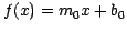 , is computed to the
subset of data points within some range
(
, is computed to the
subset of data points within some range
( , nominally
  days). Thus,
  defines our instantaneous slope or derivative at that point. The data
value interpolated from the fit at that point gives our smoothed curve.
A straight line fit on the derivative array gives us a single metric
to call the second derivative.
With the first and second derivatives we can extrapolate out some
length of time (nominally 6 months) to look for future limit violations.
defines our instantaneous slope or derivative at that point. The data
value interpolated from the fit at that point gives our smoothed curve.
A straight line fit on the derivative array gives us a single metric
to call the second derivative.
With the first and second derivatives we can extrapolate out some
length of time (nominally 6 months) to look for future limit violations.
3. Data Output/User Interface
The URL for SOT Trending is
http://cxc.harvard.edu/mta/DAILY/mta_deriv.
Figure 1:
Example dtrend summary pages. Note columns 4 and 5 on the right,
which show the linear fit slope of the data (first derivative) and
the fit to the ``instantaneous'' slopes (second derivative),
respectively.
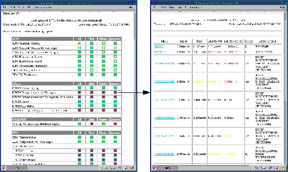 |
Figure 2:
Examples of mnemonic vs. time (left) and
correlation (right) plots. Each shows cleaned data, smoothed curve, and
fit line on top along with first and second derivatives in bottom panel.
The time-dependant plot has a six month extrapolation while
the correlation features a color bar to indicate time.
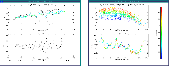 |
Figure 1 shows example summary pages.
On the left is the trending top level page.
Here we present a table listing all the trended subsystems with links to the
available analyses (total, daily minimum, daily maximum, and past
quarter). The links are color-coded green, yellow, and red based on
limit violations seen in the underlying pages to quickly
identify the problem areas.
On the right is a subsystem summary and statistics page.
Each link from the top level page
expands to a statistical summary
page. Here we list for each mnemonic
the calculated mean, standard deviation, first derivative, and second
derivative. These values are color-coded to easily
identify the current or future problem areas. We also list units and a
description of each mnemonic extracted from the limits look-up
file for reference.
Figure 2 shows examples of our pop-up plotting windows.
Each mnemonic links to a plot of the data. The top panel in each shows a
scatter plot of the data
with smoothed curve (blue) and fit line overplotted. Note the six month
extrapolation plotted based on the second derivative.
Any out-of-limit values are indicated with yellow or red colors.
There are several types of profiles commonly seen:
On the left is a linear fit,  ,
for simple cases or as a first step in cases not yet understood.
,
for simple cases or as a first step in cases not yet understood.
The right-hand figure shows that we do not have to plot only versus time.
Here we show temperature
versus sun angle, with time indicated by the color of the data points.
It is clear that the
EPHIN housing heats up most at forward-sun attitudes,
but the problem is getting worse
over time due to the deterioration and darkening of insulating materials.
This profile may be best fit
with a higher order polynomial or exponential decay model, such as
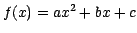 or
or
 .
.
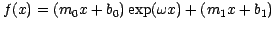
Other subsystems show more complicated structures, with multiple components.
Solar array voltages, for instance, show an overall decreasing linear or
exponential trend as
well as seasonal sinusoidal variations. By carefully fitting both of
these elements
with something like
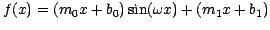 ,
we can glean more information on the system's behavior and
better estimate its future performance.
,
we can glean more information on the system's behavior and
better estimate its future performance.
Acknowledgments
This work is supported by NASA contract NAS8-39073.
References
Overbeck, R. S. et. al. 2002, in ASP Conf. Ser., Vol. 281, Astronomical Data Analysis Software and Systems
XI, ed. David A.
Bohlender, Daniel Durand and T. H. Handley (San Francisco: ASP), 449
Spitzbart, B. D., Wolk, S. J. & Isobe, T. 2002,
in Observatory Operations to Optimize Scientific Return III,
ed. Quinn, Peter J., Proceedings of the SPIE, 4844, 476
Wolk, S. J. et. al. 2002, in ASP Conf. Ser., Vol. 281, Astronomical Data Analysis Software and Systems
XI, ed. David A.
Bohlender, Daniel Durand and T. H. Handley (San Francisco: ASP), 341
© Copyright 2004 Astronomical Society of the Pacific, 390 Ashton Avenue, San Francisco, California 94112, USA
Next: Evaluation of Methods to Locate Emission Lines From Calibration Lamps in 2D Spectroscopic Data
Up: Data Processing Systems
Previous: Maintaining Software for Active Missions: a Case Study of Chandra's CTI Problem
Table of Contents -
Subject Index -
Author Index -
Search -
PS reprint -
PDF reprint